

Cogenerative Energy

Cogeneration thermoelectric plant
Cogeneration plant
The research department of CREA Ltd company designs cogeneration plants powered by renewable sources. Any type of fuel is theoretically suitable for this purpose and it is also possible to use energy recovery from other industrial processes. The choice of the energy source, therefore, depends exclusively on its cost, its availability on-site and its environmental impact.
Biomass

The cogeneration plant can be designed to use lignocellulosic biomass as a combustible material. The biomass in question derives directly from the activities related to forests and agricultural practices: recoveries of coppicing waste, firewood, by-products of the wood industry such as sawdust, hedges and crops prunings, by-products of farms, etc. The most widespread solid fuels are firewood, wood chips, pellets and forest residues. In particular, “wood chips” or “shredded wood” are defined as flake wood obtained from special machines capable of grinding wood logs. In order to produce wood chips, lower quality wood is normally used, such as agricultural or urban pruning residues, waste produced by sawmills or even the wood of tree species specially grown in plants with short rotation (SRF).
Flake-reduced wood can be absorbed by the market to be used in the production of particle boards, in the paper industry, in the production of compounds or for energy uses.
Fuel derived from solid urban waste SRF/RDF (Solid Refused Fuel / Refuse Derived Fuel)

The major problems associated with the use of this fuel derive not only from the management of waste and landfills but from its poor acceptability on the part of the population, which considers it a fuel with a high environmental risk. From this point of view, on the other hand, experience shows that technological development and proper management are able to provide adequate guarantees of environmental safety in the use of this fuel (without prejudice to waste reduction objectives and priority to recycling and reuse).
In fact, the European Directive 2000/76 / EC defines the emission limits and the control systems for the so-called “co-incinerators”, whose main purpose is not the elimination of waste but the generation of energy and the Legislative Decree. 387/2003 has included the waste among the energy sources eligible for the treatment of renewable sources.
Steam plants
Through the use of appropriate mathematical models, the research area of the CREA company can design steam boiler-turbine systems that can operate with condensation, bleeding or backpressure. With these systems the thermal power is transmitted in one of the two following ways:
- removing part of the steam from the turbine before it has completed the expansion;
- using the steam produced by heat recovery from the turbine discharge.
The purpose of these systems is to transform the thermal energy owned by water vapor into mechanical work. From the thermodynamic point of view the engine usually develops a Hirn Cycle in which the heat carrier is made up by a mass of demineralized water that comes:
- Entered by means of a PUMPING system in the upper manifold up to the pressure required by the steam generator.
- Heated inside a STEAM GENERATOR which usually develops in “falling pipes” towards the lower manifolds which, in turn, feed the “rising pipes” towards the upper collecting body with saturated water. The ascent pipes constitute the heat exchange section (VAP), where the water receives the vaporization heat from the fumes (these pipes continuously occupy the containment wall of the combustion zone directly above the hearth) while the descent pipes, especially in the final part of the hearth of the combustion chamber protected by the refractory material, are not involved in the heat exchange process.
- Passed in the form of steam inside an OVERHEATER in contact with the hot fumes coming out of the hearth, so as to increase the temperature and the enthalpy of the steam itself before it reaches the turbine.
- Made to expand in a STEAM TURBINE to produce work that powers an electric generator.
- Bring back from the mixed steam state to the liquid state by condensing the steam discharged by the turbine (now unusable because of too low pressure) in a CONDENSER in which the steam flow is put in contact to another cooler water mass which removes heat from the steam. The water is then returned to the PUMPING system and, then, the cycle restarts.
A schematic representation of a Hirn Cycle for a waste-to-energy plant with progressive tapping is shown in Figure 1.

Figure 1 Organization of the tapping in a Hirn Cycle waste-to-energy plant with progressive tapping – Source CREA S.r.l.
The thermodynamic cycle scheme of the previous plant is shown in the Entropy (s) -Temperature (T) diagram of Figure 2.
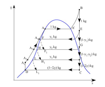
Figure 2 Representation in the T-s diagram of the Hirn cycle with tapping corresponding to the previous plant – Source CREA S.r.l.
The idea behind all the processes that use vapor leaving the boiler is to effectively recover the heat these possess, more valuable if it is higher with its temperature. The “quality” of the heat is linked, in fact, to the temperature at which this heat is exchanged because higher temperatures are synonymous with greater useful energy obtainable from the system. The bleed turbine allows greater operational flexibility depending on the variations in the electrical and thermal load, while the backpressure turbine has a greater overall yield.
The main advantages of these cogeneration systems are:
- High cogeneration yields (up to 94-95%);
- Possibility of using less valuable fuels;
- High operational reliability.
The most critical aspects, however, are:
- Lack of sizes available for small installations;
- Limited flexibility with respect to variations in heat and electricity demand.
Combustion plant
Combustion takes place on several mobile Martin push-in reverse grids, all individually powered by the loader at the slag discharge with primary combustion air and equipped with alternating fixed and movable fire bars, being inclined 22 ° ÷ 26 ° with respect to the horizontal. The combustion air is distributed under the grille as primary air and blown through rows of nozzles in the hearth above the grille as secondary air.
A heat exchanger is installed on the primary air supply duct with the function of heating this air before entering the combustion chamber. The exchanger is powered by low-pressure steam, which allows for air heating up to around 130 ° C.
The high aerodynamic resistance, given by the shape of the stable body of the steps, guarantees a uniform air supply in the combustion layer and at the same time a forced cooling of the grid. The average operating temperature of the fire bars exceeds only 100 ° C that of the primary air, with a consequent high safety against thermal overload and a high duration of operating life, which depends almost exclusively on mechanical wear.
The reverse thrust movement of the movable grid steps, which opposes the natural downward movement of the waste layer, causes them to move first upwards and then downwards. This ensures a constant mixing of the waste layers favoring combustion and preventing both local overheating and slag accumulations in the combustion bed, with a consequent excellent unburnt content. The residence time of the waste on the grid is about an hour.
The secondary combustion, ie the complete oxidation of the unburnt gases, takes place in the post-combustion chamber in the hearth placed above the main combustion area, where the unburned gases mix with the secondary combustion air and with part of the recirculated fumes, placed at high speed through special nozzles arranged in the front and rear walls of the oven. The scheme of a combustion plant for this type of incinerator is shown in Figure 3.

Figure 3 Schematic representation of a combustion plant for a waste-to-energy plant – Source: TRM S.p.A.
The positive results are a better boiler performance (less heat loss from the fumes) and a decrease in NOx production. Post-combustion takes place for at least two seconds at a temperature above 850 ° C. To ensure this minimum condition, natural gas support burners are provided, which start automatically if the temperature falls below the prescribed limit. Other natural gas burners, so-called start-up burners placed at the bottom of the grill, start operating when the furnace is started, to heat it up to a sufficiently high temperature before the introduction of the waste.
The combustion process is monitored by an automatic system capable of self-adjusting to keep the combustion parameters at optimum values, thus achieving maximum efficiency. The achievement and maintenance of the combustion parameters at optimal values is also a guarantee of limiting emissions (both solid and gaseous). The optimization of combustion and emissions is obtained through the control of the waste supply, from the movement of the grid and from primary and secondary air flows suitably governed by PLC (Programmable Logic Controller).
The chemical reactions that drive the combustion phase can be summarized as follows:
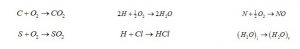
In the lower part of the grid the complete combustion of the waste occurs. At the end of the grid, each track has a slag-like cylindrical element that regulates the height of the slag layer as well as the residence time in the combustion-exhaustion zone in order to achieve sufficient coverage of the surface of the grid itself for protection against the thermal radiations coming from the hearth. The burnt slag slides on the relative cylinder in the hopper and falls through the next intermediate log into the slag extractor, where a water bath guarantees complete shutdown and cooling, moistens it facilitating removal without dust or odors and creates a barrier to seal preventing penetration of infiltration air through the slag extractor (Figure 4). The slag extractor is also conveyed, thanks to special evacuation ducts, the slag particles that fall in minimum quantities through the gaps and the air slits between the bars of the grid.

Figure 4 Section for waste recovery – Source TRM S.p.A.
Thermal recovery section
Each waste-to-energy line is equipped with a heat recovery steam generator, capable of cooling the combustion fumes using the sensible heat taken from them to produce superheated steam to be sent to the thermal cycle common to the waste-to-energy lines.
The steam generator is of horizontal type with water pipes, natural circulation and a single cylindrical body, with three vertical radiating channels and a horizontal convective part. The generator structure is of the type with membrane wall (welded panels with fins and pipes). Water flows through the membrane walls, both as a cooling medium and as a heat recuperator given off by the combustion of waste. The water that circulates in the pipes, in fact, is under pressure and when heated with the heat of the fumes evaporates, going to feed the turbine. The water used for steam production is demineralized water (Figure 5).
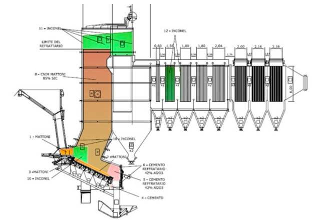
Figure 5 Thermal recovery section – Source TRM S.p.A.
The first three channels are called radiant because the heat exchange between combustion fumes and membrane pipes takes place essentially by radiation (fumes temperatures above 600 ° C).
The fumes then pass through the convective section of the boiler, where the heat exchange takes place mainly through convective procedures. The steam generator ends with an economizer which has the purpose of cooling the fumes up to 200 ° C before treating them.
The steam generator is equipped with a single cylindrical body placed transversely above the rear wall of the second radiant channel and performs two fundamental functions: one is the separation of steam from water, so as to supply the system downstream with water steam-free for correct and safe circulation inside the steam generator. The other is the separation of the condensate from the steam to allow a high purity of the steam, from which the last drops of water are extracted before heating it with superheaters up to the temperature of 420 ° C and send it to the turbine.
A solution with a horizontal boiler is preferable to the more compact vertical solution due to the greater efficiency obtainable in cleaning the pipes. A second reason, which favors the choice of a boiler with a horizontal configuration, is the relative ease of rapid extraction from above by installing a service crane, positioned inside the building that houses the boilers, in order to facilitate maintenance operations.
The use of special “water lances” allows the radiant section to be cleaned. A “hammer system” also allows the removal of fly ash, deposited on the external surfaces of the exchangers in the convective channel.
At the points where the boiler walls are subjected to the highest temperatures (first section of the first radiant channel) silicon carbide refractory slabs are installed, with protection functions. Furthermore, due to the presence in the fumes of acid and chemically aggressive substances (alkaline-metal salts), some parts of the boiler most exposed to corrosion are protected with Inconel 625 coatings. Between them, the first radiant channel above the refractory zone, the vault between the first and the second radiant channel, the second radiant channel and the superheater placed in the warmest area of the convective channel (see parts in green in Figure 5).
The plant is always equipped with an automated command and control system, which allows the operators in the control room to optimally manage all the process parameters. A software links the basic combustion parameters in real-time (boiler temperature, fuel temperature, oxygen, airflow, waste load, % smoke recirculation) and self-regulates them. In this way the operation is optimized, which is therefore constant and homogeneous thanks to small adjustments which, from an environmental point of view, eliminate the temporary peaks in the production of CO and other micro-pollutants.
Energy production plant
The energy production plant has the task of converting the steam produced in the boiler from the combustion of waste into electricity through a “steam turbine” and to supply steam for district heating.
In the vaporizing circuit, for the purposes of efficiency, the ratio between the steam flow rate and that flowing in the water pipe circuit is very important. The steam generator is developed in “fall pipes” towards the lower manifolds which feed the “rising pipes” towards the upper cylindrical body with saturated water. The ascent pipes constitute the heat exchange section, where the water receives the vaporization heat from the fumes while the descent pipes, especially in the final part of the combustion chamber firebox protected by the refractory material, are not involved in the exchange process thermal (Figure 6).

Figure 6 Schematic representation of the water pipe boiler – Source CREA S.r.l.
The exhausted steam from the low-pressure stage of the turbine is then returned to the liquid state, in a water-cooled condenser with industrial water (main condenser). From here the water of the thermal cycle is preheated and pumped into the heat exchangers of the boilers to restart the cycle.
The steam enters the main condenser from the shell side while the cooling water circulates on the pipe side. An auxiliary condenser, connected in series in series with the main condenser and normally in standby conditions, guarantees an immediate intervention on the reduced steam by the by-pass valves, in case of turbine failure.
In these enthalpy conditions, the turbine, coupled with an electric generator, is able to produce, in an electric-only configuration, a gross electrical power at the terminals of the alternator of about 3.80 MW per t / h of steam generated.
The cooling of the water circulated in the two condensers takes place in “wet-dry” evaporative cooling towers, which ensure the transfer to the atmosphere of the condensation heat of the steam (Figure 7).

Figure 7 Schematic representation of the closed circuit made for cooling the condenser cooling water – Source CREA S.r.l.
Fume treatment plant
From the cylindrical body placed on the top of the boiler comes the saturated steam, which flowing through other tube bundles, the so-called “superheaters”, placed at the entrance to the convective section of the boiler, where the fumes are warmer, turns into superheated steam for then enter at a temperature of 420 ° C and at a pressure of 60 bar in the steam turbine, which is able to receive all the steam produced by the boilers.
The fumes treatment plant has the task of minimizing the concentrations of pollutants present in the fumes coming from the combustion of waste. The choice of plant technologies is made by the CREA research group in accordance with the best technologies currently available on the subject of containing emissions. This choice involves a “dry” system with double-stage dedusting, which allows a deduster (electro filter) to be dedicated to boiler dust removal and one (bag filter) to absorb the adsorbents.
Figure 8 shows an example of a fume treatment plant.

Figure 8 Fume treatment plant – Source: TRM S.p.A.
pores of the fabric of which they are made, contributes to increasing the degree of advancement of the purification reactions already started in the dry reactor, significantly increasing the efficiency of everything the fumes treatment process.
- Continuing along the path of the fumes leaving the bag filters at a temperature of about 180 ° C, the last stage of flue gas purification foresees a catalytic system for the abatement of nitrogen oxides (NOx).
It is a reactor divided into two parts:
- A mixing zone in which the fumes from the bag filter are added with ammonia containing gas (NH3) at 3 ÷ 4%;
- A treatment area where ammonia reduces the NOx of the fumes, reacting with them thanks to catalyst substances.
The ammoniacal vapors, injected into the mixing zone, come from a separate reactor, where urea (CO(NH2)2) in aqueous solution is decomposed to produce ammonia (NH3) thanks to the heat produced by a natural gas burner. In the process of reducing nitrogen oxides (selective catalytic reduction or SCR) the nitrogen oxides present in the fumes are reduced to water vapor and nitrogen by reacting with ammonia. To increase the reaction speed to the temperature in the fumes, catalysts are used which consist essentially of titanium oxide (TiO2) and of tungsten oxides (WO3) and vanadium pentoxide (V2O5) used as additives.
To ensure intimate contact between the fumes, ammoniacal vapors and catalysts, honeycomb septa are placed in the SCR reactor treatment area, on whose surfaces the metal oxides catalysts are fixed.
The catalytic system, to carry out its NOx abatement capacity, uses the following chemical reactions:
- Thermal decomposition of urea

- Catalytic reduction

At the end of the treatment units there is a fume extraction fan for each waste-to-energy line, which allows the entire line to be maintained in depression starting from the waste pit.
Through a dedicated silencer the purified fumes of each line are fed to the respective expulsion flue.